
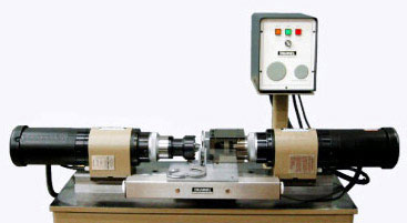
Taumel Orbital Forming Process
Taumel Orbital Headforming Machines have been used to assemble a variety of stamped and blanked components for more than 40 years.
With the introduction of flexible manufacturing and advanced productivity concepts, including just-in-time (JIT) manufacturing and measurable process control, the use of orbital headforming in production has increased.
Orbital Headforming (which is sometimes called orbital forming) is a clean, silent, non-impact, and vibration-free cold-forming process. Often, it can be used as an alternative to conventional staking, peening, crimping, pressing, swaging, spinning, rolling, riveting, welding, upsetting, and other fastening operations.
An orbital headforming machine flares studs, pins, posts, hubs, spacers, rivets, and other fasteners quickly.
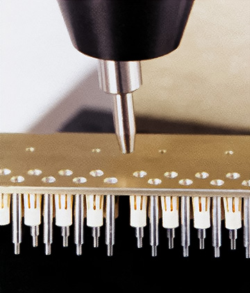
If one or more shoulder pins must be secured to a blanked plate, a single-spindle machine can be used to secure one pin at a time, or a multi spindle system can be used to flare any combination of pins, hubs, or posts on the same work piece.
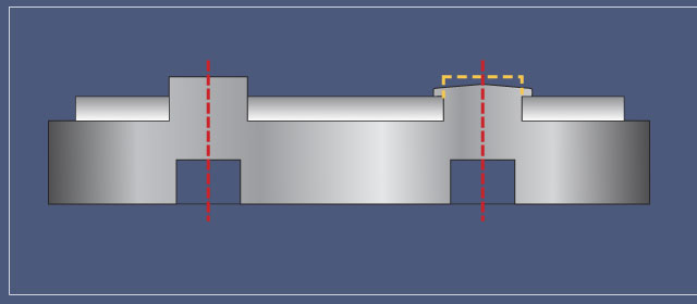
The process also can be used to assemble components without fasteners. This image illustrates semi-pierced studs on a fine blanked part being flared over a mating plate.
On an appliance part, two to four bent-up tabs on a stamped mounting plate may be designed as spacers that fit through through matching square or rectangular holes of a mating cover plate.
An orbital headforming machine then can be used to flare these tabs for a secure and correctly aligned assembly without fasteners.
High-torque joints
in solid or tubular form in stamping assemblies may be produced in many ways with orbital headforming machines.
Blanked holes in a plate may be designed in D or double-D configurations, often with provisions for specific part orientation.
Shafts or tubes with the matching D or double-D shapes can be made to protrude through the stamping for assembly on the headforming machine.
Similarly, round shoulder pins may be flared in punched square holes of a mating plate, allowing the headforming machine to cause available material to flow into the corners of square holes.
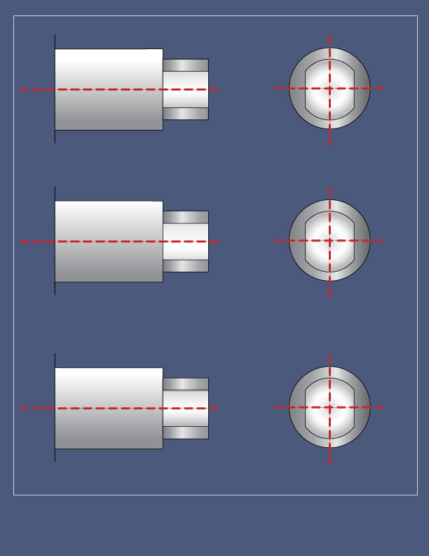
Further, one or more round posts or square tabs protruding through punched holes in stampings can be headformed. Notches or serrations may be blanked into round holes to increase the contact area and improve torque resistance after the part assembly.
Compared to any Press method, the orbital process requires 12 to 15 percent of the forming forces. The reason is the same as that used to explain how a 100-pound woman can gouge dents into hard flooring when she wears spiked heels, while a much heavier person wearing flat-bottomed shoes does not.
Orbital headforming uses less force but concentrates it on a continuos radial line emanating from the center of the shaft, rather than over the entire area to be formed. This prevents damage to the opposed, threaded shaft end of mating part, facilitates the part's support, and allows for the use of simplified fixture tooling.
Likewise, orbital headforming often eliminates the need for separate hardware; blanked ridges, bosses, and integral projections of malleable material can be formed out to anchor components in position.
For example, a leaf spring may be captured on a stamping by flaring two blanked rib sections with a single form tool.
The Orbital Process:
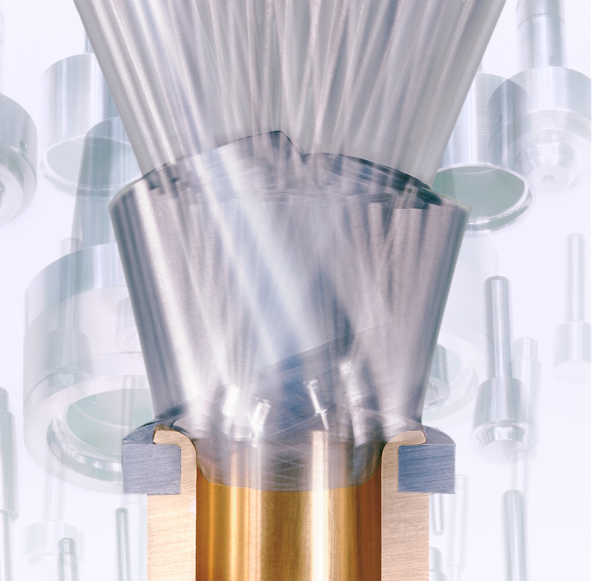
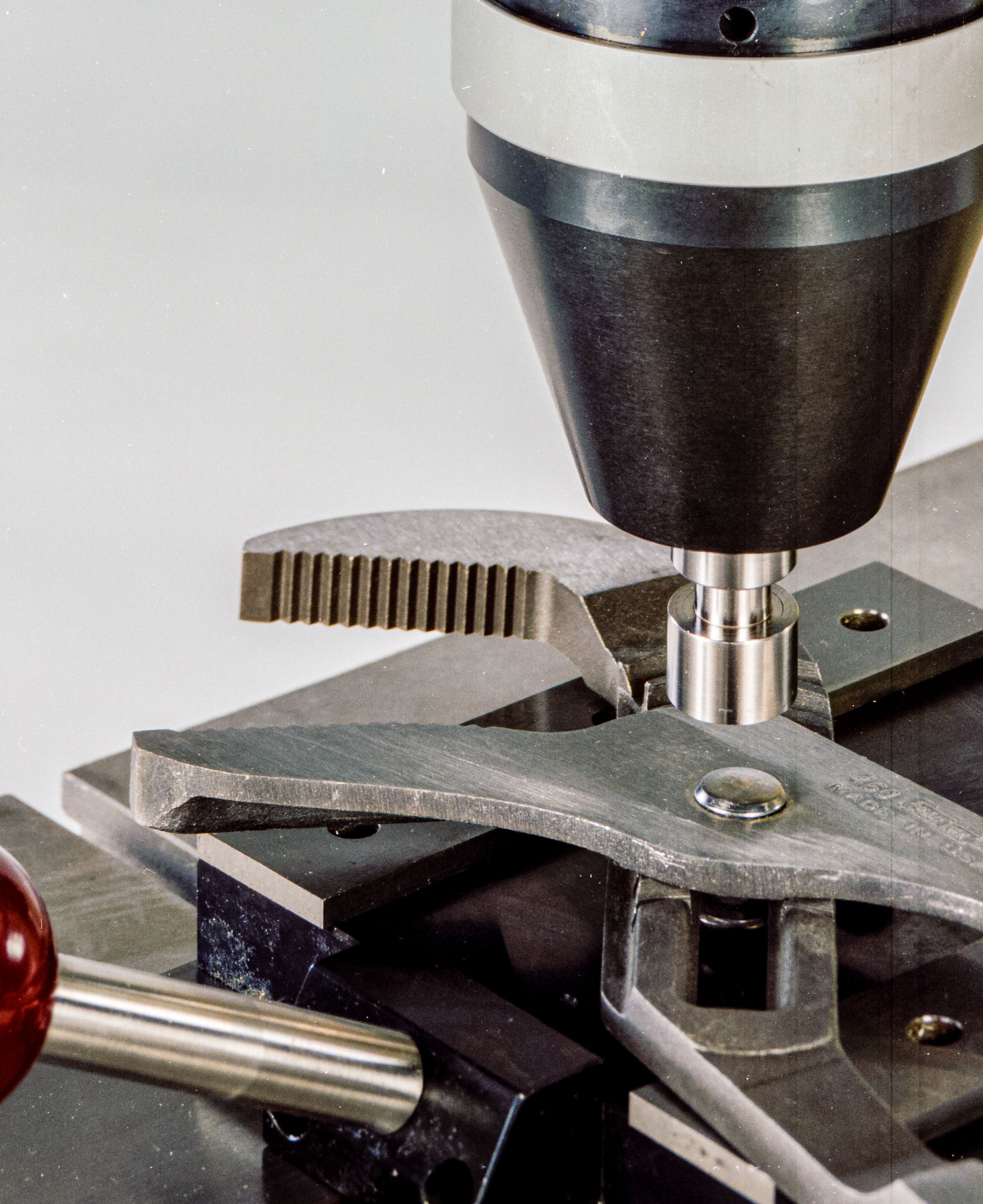
In orbital headforming a form tool, mounted off-center in a revolving spindle much like a tool in a jig-borer, is inclined at a slight angle toward the center of the spindle.
The tool axis of the form at the working end of the tool intersects with the true centerline of the spindle. the machine spindle rotates, but the tool in the orbital head or chuck is free to rotate in its bearings. The drive spindle advances, bringing the tool into contact with the work piece.
Multiple-point forming:
Multiple-point forming on a single work piece or gang heading multiple parts is possible, with many variations. An orbital headforming machine can be configured to carry as many tools as needed and with centers as close as 3/16 inch to meet multi-task applications. Larger multi spindle systems may have tooling plates up to 20 inches across, often with tools working at different heights or heading levels and on more than one part simultaneously.
Changeable tooling sets
allow simple conversion from one heading pattern (job) to the next. Standard multiple attachments, in-line and random pattern tooling and two, three, and four variable-center-distance spindles--fit most machines.
Double-Ended, Opposed Heading:
For double-ended, opposed heading, two modular heading units generally are mounted horizontally on a machine bed, facing one another. This configuration allows cut rods, shafts, or tubes to be used, as well as cutoff and feed devices to load the machine.
Swing-Joint Forming:
The precise stroke control on orbital headforming machines makes possible the production of pliers, scissors, pocket knife joints, surgical sutures, gear trains, bobbins, handcuffs, or any swing-joint assembly as "tight swing", "loose swing", or "floating", as desired.
Non-round Headforming:
Single- or double-D solid shafts (square, rectangle, and oval) can also be orbitally formed. Three rectangular studs can be simultaneously headed with a single large, round tool in a single-spindle orbital head, for example.
Aspects of the Process
Cycle Time: As a rule, shorter cycle times in manufacturing operations result in better production rates. In general, cycle times for orbital headforming run from 0.5 to about 2.0 seconds on solid steel studs of higher tensile strength. This includes tool approach, heading dwell, and spindle return but not part loading.
The softer and more malleable a material is, and the smaller its diameter, the shorter the work cycle is. However, even on steel pins 1.0 inch in diameter, cycle times are about 2 seconds. When automatic slider plates or index-type fixturing are used, the time required to load parts manually or automatically has a larger impact on production rates than does cycle time.
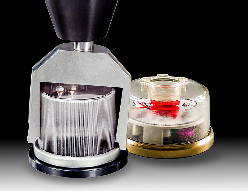
Heading Capacity:
Heading capacity for any size of machine is governed not so much by the diameter of the figuring as by the total surface area to be formed and the material's tensile strength. For example, a machine that can flare a 5/16-inch-diameter solid shoulder pin in mild steel can be used to swage over the shell of a Type D flashlight battery to crimp or seal its end. It can also flange a tube or a 3-inch-diameter hollow aluminum body that has a wall thickness of 0.030 inch.
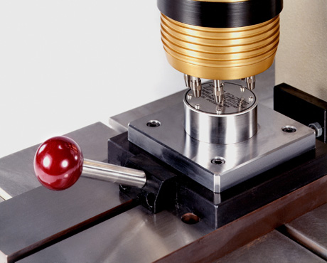
Fixturing:
Parts placed or fed into the fixture of an orbital headforming machine usually can be left freestanding and require no clamps or hold-downs. No spinning force is transferred from the work head to the parts, so they remain where they are placed through the cycle. For example, a two-plate assembly to be joined by one rivet usually requires a simple locating nest with a pocket to position the pre-formed rivet head.
Stud Placement:
Hard-to-reach pins can be dealt with by orbital headforming.
A shoulder stud may be secured close to a vertical wall or in a recess of a part. The reach of the tool is limited only by the clearance around it while it is orbiting. Changing the angle of the tool by as little as two degrees can reduce the clearance requirement.